Radar vx vy and vx_comp vy_comp

Hi
Do the speeds vx and vy of the radar points represent relative speeds? Are vx_comp and vy_comp the ground truth speed values ​​of obstacles? Do we have no way of knowing the movement status of the Renault Zoe car that collected the data? Is it possible to know the possible movement direction of obstacles through radar?

Thanks

I also have similar questions:

Do vx and vy of the points represent the velocity of the points in radar frame?
If yes, is there some kind of additional algorithm like tracking? Because a radar can only estimate radial velocity in its own frame.

What is the physical meaning of vx_comp and vy_comp?

Hi,

Do the speeds vx and vy of the radar points represent relative speeds?

These are velocities in m/s in the current radar frame. I guess you could call these relative, because if our ego vehicle moves forward at 10m/s, a stationary vehicle in front of it should have a velocity of -10m/s.

Are vx_comp and vy_comp the ground truth speed values ​​of obstacles?

Note that there is no ground-truth here. All measurements are noisy. The compensated velocities are compensated by ego motion.

Do we have no way of knowing the movement status of the Renault Zoe car that collected the data?

Yes, look at the ego pose table, which gives you very accurate poses of the ego vehicle.

Is it possible to know the possible movement direction of obstacles through radar?

Yes, look at the compensated velocities.

Do vx and vy of the points represent the velocity of the points in radar frame?

Yes.

If yes, is there some kind of additional algorithm like tracking? Because a radar can only estimate radial velocity in its own frame.

Please elaborate.

What is the physical meaning of vx_comp and vy_comp?

It is the measured velocity minus the ego motion.

Thanks for replying my questions.

radar_target
Let a point/target has a velocity v. Normally a radar can only measure radial velocity vr, not vx and vy. Normally vx and vy are estimated using data over a period of time with algorithm like tracking.

1 Like

That is correct. The radar measures the angle alpha and range vr to the sensor. The vx and vy provided by the radar are simply the x and y components of vr (vy = sin(alpha) * vr, vx = cos(alpha) * vr).
In the nuScenes tutorial (https://www.nuscenes.org/tutorial) you can also see an example, of how all the radar velocity vectors point towards the ego vehicle (the red cross).

I’ve also had trouble interpreting the radar velocities as they did not behave as one would expect.

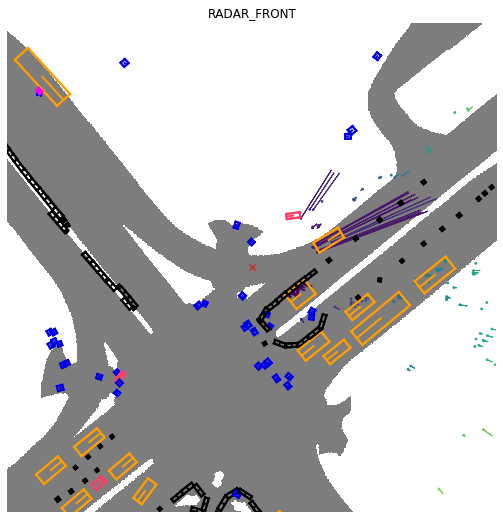
To illustrate the point, I’ve arranged a GIF from test scene 343. The ego-vehicle starts moving at t=5s, while the GIF shows raw detections from front radar in it’s coordinate frame accompanied by uncompensated (blue) and compensated (red) velocities.

It raises several questions:
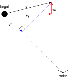
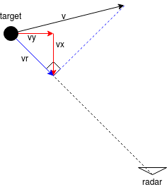
1.) It is odd that the uncompensated velocities do not point towards the radar, while they definitely should if they are raw measurements as the isrohutama’s illustration points out.
I had an assumption that the field vx contains the raw range rate for the detection, but it can be seen that field vy is not always 0 (mostly it is). Thus, it is difficult to interpret vx and vy.

2.) How are the velocities compensated in (vx_comp, vy_comp)?
By observing the static detections (building walls on both sides), we can notice that compensated velocity is zero, Thus, I assume that the these are correctly compensated radial velocities. However, it is not clear how to compensate (vx,vy) to obtain (vx_comp,vy_comp).

3.) Is the compensation performed by the radar processing algorithms or later in postprocessing?
If it’s done by the radar, did it receive vehicle speed and yaw rate that some radars take as an input over CAN, or did the radar perform it’s own ego motion estimation?

Hi @holger-motional ,

Thanks for replying.
Is this what you mean?
radar_target_1

If it is like above picture, vx vy vector should point toward the radar. I evaluated scene-0757 and it doesn’t point toward the radar.

I also checked vx_comp vy_comp vector and it points toward the radar like what you said.
Assuming vx and vy are like above picture. Is the following how vx_comp and vy_comp are obtained:

  1. A point with measured position [x y] and measured radial velocity [vx vy]
  2. [vx_s vy_s] is the expected radial velocity if a point at [x y] is static (considering the ego motion).
  3. [vx_comp vy_comp] = [vx vy] - [vx_s vy_s]
1 Like

Please contact holger@nutonomy.com and I’ll send you the detailed radar documentation. For the compensation, we pass the localization info to the radar.

It looks to me like the radar adds an angular velocity component that is proportional to the vehicles yaw rate based on the range to the target. My guess is that if you get the IMU yaw-rate and subtract that angular component then the raw vx and vy values will point back to the radar.

Could you please explain in more detail how you came to that conclusion?

In the scene shown by the GIF I previously posted, the car is at standstill and then it starts moving forward. Since the yaw-rate is approx. 0 all the time, such compensation would not correct (vx,vy).

Hi,
i have also problems grasping some of these points. For example :

  • The velocities vx and vy are in the radar frame as Holger pointed out and the example he mentioned makes sense as a stationary vehicle would be assigned the negative velocity of the ego vehicle. What in my opinion makes less sense is that the the compensated velocity is computed by subtracting the velocities vx and vy from the ego velocity vx_e and vy_e because that would mean that a stationary vehicle has velocity vx_comp = 2vx_e and vy_comp = 2vy_e which is not correct. The velocities should be added instead of subtracted in my opinion to get the velocity of the object relative to the global coordinate system.

  • It is still unclear how the radar gets the ego vehicle velocity to perform the compensation, as @jurajpersic asked in his 3rd question. This would really be helpfull.

Thanks.

1 Like

Yes, in general the velocities are added.

In my opintion, your idea is right. The principle of radar can only measure the radial velocity(Doppler velocity) and lose tangent velocity. So we can’t get the relative velocity betweeen radar and target and use some methods as what you see:

Normally vx and vy are estimated using data over a period of time with algorithm like tracking.

Our lidar does not measure velocity, hence I believe this is not relevant.

I want to convert the radar sensor’s speed information (Vx, Vy) back to a doppler velocity measurement to test our algorithms. Can you please be more specific, which data is fed into the radar sensor as “Yaw Rate Information”?

There is also the possibility to give a velocity information as input to the radar sensor, but I believe, you only use the yaw rate input. Am I correct in assuming that?

Hi @holger-motional ,

Based on you metioned before,

The radar measures the angle alpha and range vr to the sensor. The vx and vy provided by the radar are simply the x and y components of vr (vy = sin(alpha) * vr, vx = cos(alpha) * vr).

The vector “v” compose of vx and vy must point from radar origin to radar point,
as @jurajpersic show the GIF that the vector “v” does not point that way, but “v_comp” does.

My questions are:

  1. Could you please explain why the vector “v” behave that way ?
  2. Could you please explain how the “v_comp” is created, and make it point to the right radial direction ?

Thank you very much !!